Window maker and dockapps nostalgia

wmapcups

Tried a bit of nostalgia driven “comfort” programming making wmapcups. It is a Window Maker dockapp that presents the status of an APC UPS via the apcupsd.

Window maker itself is a bit dated compared to the ‘desktop managers’ these days but it is fast if can look past that. If your keyboard sees more action than your mouse and you don’t want to to overboard with tiling window managers this is a good trade off. I use window maker at work on one of the older PCs while the newer ones run xfce4. I use dockapps under Xfce through a panel plugin called xfce4-wmdock-plugin which gobbles up X11 programs that provide the hints that they are dockapps.

My running dockapps in xfce4 panel plugin.

Dockapps are widget-ey programs with UI made of a small square (64×64 or 48×48 pixels) mostly presenting some information. Most dockapps would serve some purpose now handled by panel (or taskbar) plugins except they have the same consistent ‘square’ tile feel. The whole ‘style’ of window maker and dockapps is inherited from the NextSTEP OS.

To write a dockapp, some familiarity with X11 programming would be useful. However its quite simple to glean the essence of it from the existing dockapp sources. Also there is library called libdockapp that wraps up the most common pattern used in the sources. For pythonistas there is a module for writing dockapps as well (I’ve not tried it yet).

Window maker development was dead for many years during before being started up again in 2012. The current team accepts patches for window maker and few orphaned dockapps that they’ve adopted.

Wifi CLIP v1

Wifi CLIP Thingy

Forgive me for the click-bait summary. Well, what I said there is not entirely false.

Its been more than just more than a year since I re-started my electronics hobby (since some 16 years ago, I guess). Around that time (1 year, not 16 years) an oldish DIY project article on the Internet clued me in that caller ID was transmitted as DTMF tones (in India). It was true, I even could read the info with CM8870. Within a a couple of months I noticed that the DTMF business was not working but my phone was displaying the info – which means the exchange did not disable the feature. This meant they switched the signaling. Couple of experiments with an opamp and DSO proved it – they were using FSK (wiki)

The 3 portions of the CLIP signalling.

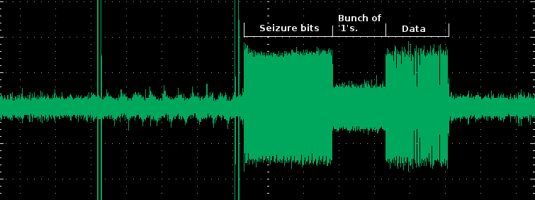
The 3 portions of the CLIP signaling.

Then came the futile attempt to demodulate it using a CD4046 (PLL). Lot of trial and error but could not get clean bits out of it – something to do with lousy low pass filter design. After some googling I came to the standalone decoder chip HT9032. It does the demodulation and gives us plain logic output. There are two variants of this chip, the ‘C’ and ‘D’ – the D version is the smaller one with 8pins but does not offer ring detection (that has to be done separately).

Portion of the FSK signal

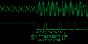
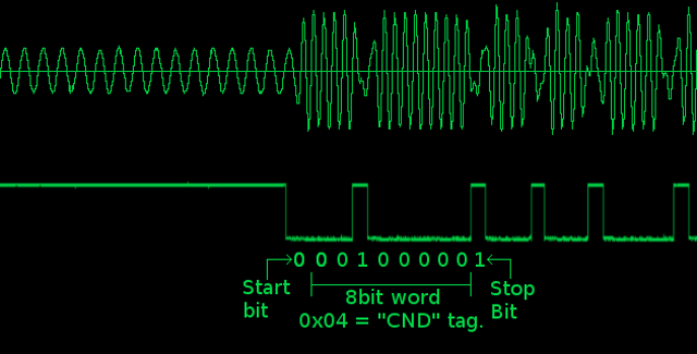
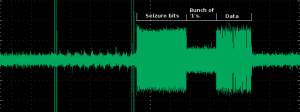
Portion of the FSK signal (at the boundary of the stretch of ‘1’s and the data)
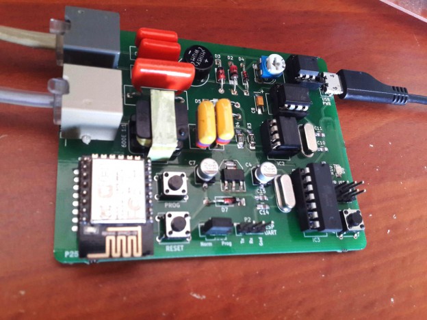
Hardware

There are four blocks in the circuit

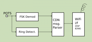
There is always a block diagram !!! (POTS = telephone line)

  1. FSK Demodulator which converts the FSK signal to stream of UART like bits
  2. Ring detector which give a logic high when the high voltage ring signal arrives.
  3. Caller ID message (CND) Parser which pulls out the data fields from frame of data
  4. Wifi interface that dispatches the info for fun and profit.

The Telephone decoupling

Transformer's revenge

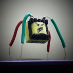
Transformer’s revenge. I had pulled out a fallen transformer (from an ADSL splitter for first experiment – its not a 1:1 transformer).

The telephone lines (called TIP and RING) don’t have ground reference so we can’t really stick it on to one of our chips (unless it knows what its doing). One usually has to use a 1:1 transformer with (600 ohm facing the PSTN line) to get the signal – I’ve used one of those to get the audio signal for HT9032 to devour. The ring detection is separated using an opto-coupler (4N35, its a ‘jelly-bean’ variety I think).

I once tried not using the 1:1 transformer and instead using just capacitors – all sort of noise from micro-controllers went back up the line – so, that’s not a good way to do it.

Key interconnects

  • The ring detector output (from the LM393) goes to the ATTiny84 PA1 (Port A, bit D1)
  • Demodulated logic stream from HT9032 goes to ATTiny84 PA2.
  • The unpacked number info (or error) goes from ATTiny’s PA0 to the UART0 RX of the ESP8266 module.

A portion of the schematic.

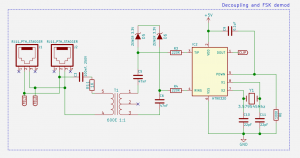
A portion of the schematic. Click the pic for the full schematic.

There is a jumper on the ESP’s UART0 RX line to select between ESP’s serial programming input and the ATTiny’s output.

Software CND parsing

The message frame that comes from the demodulator mostly carries only one type of message the ‘CND’ (Caller Number Delivery). Telephone company may provide other kind of services for e.g. CNAM (not seen any of those). I used an Arduinoâ„¢ clone in the first prototype to parse the message and send it for further processing. I later used an ATTiny84 micro-controller. The parser is not stable as the logic stream is not rock solid in pulse width as a typical UART signal (although the framing is same). I’ve added lot of fuzzy guess work to figure out the bits (You can check out the source code and suffer).

CND Message

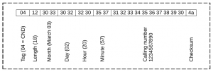
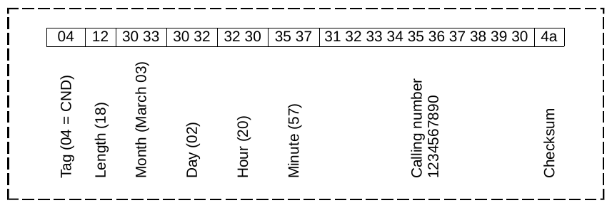
CND Message. The message bytes are in hex – the date, time and number are ASCII text. Summing up all the bytes including the checksum should have remainder of 0 when divided by 256 (Which I don’t do in the code).

Forwarding over WiFi

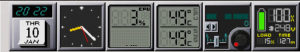
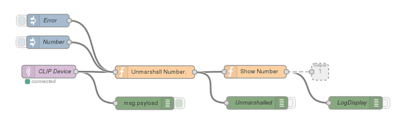
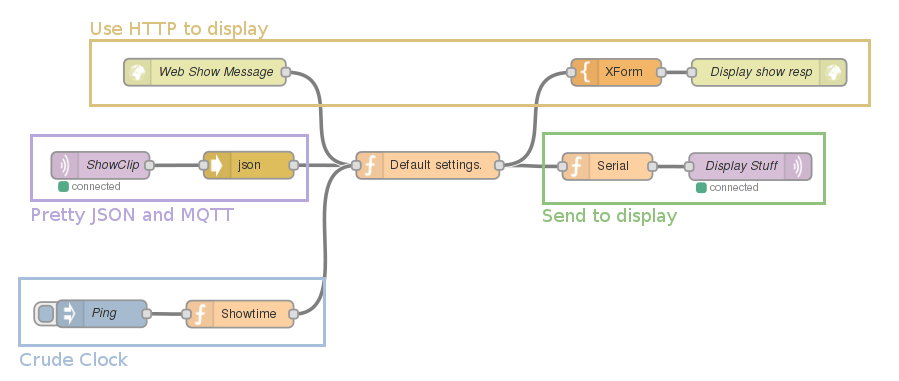
The star of 2015 ESP8266 does the job of forwarding the CLIP info. I’ve continued the use of Raspberry-Pi and Node-Red + mosquitto combination I mentioned in my earlier post about dot-matrix display. This time the ESP “publishes” the information to (or ‘as’ ?) the topic /clipdev on the MQTT agent running on the Raspberry Pi. A sample flow available at aniline/clip_display_flow.json does that and sends it to the dot-matrix display. If you want to try it you can copy the JSON text and paste it in new flow sheet on the NodeRed UI. After that you can select the portion that grabs the CLIP info and save it as a sub-flow or attach other elements to it.

Portion of the CLIP grabbing flow. Why make a single function when you could have fun with all those boxes.

Portion of the CLIP grabbing flow. Why make a single function when you could have fun with all those boxes.

Some fixing needed, what next, etc.

  • Reliability (read usability): The de-modulator spew out wrong bits occasionally.
  • Power supply regulation is non-existent on the existing prototype and right now I run it using a mobile phone charger with a USB micro-B connector at its end.
  • There are lots of ‘defensive’ / conservative telephone decoupling. It could lose some zener diodes and capacitors.

This happens to be my first more involved use of Kicad. Had made a couple of symbols, foot-prints and 3D models for this. They are available on github (links below).

Links

There are a bunch of nice articles on various methods of interfacing here:

MQTT Display

I had been fooling around cheap ESP8266 based modules. Running HTTP server to do the network end of module. It never felt right because it felt too heavy and clunky, the web server, often having trouble with concurrent connections. However the combination of Node-Red and MQTT really looks promising – learned it from Peter Scargill’s blog. I used tuanpt/esp_mqtt and a Max 7219 based dot matrix driver on arduino to build an MQTT display. So it subscribes to topic like /leddisp1/show and various kinds of messages (though I had originally meant for it to show caller-id info for my wired phone).

The board itself is a kludge and you’d find lot of connectors left open for experimentation. The ESP8266 module communicates with the Arduino Pro Mini clone (5V, 16 Mhz) via SPI with ESP acting as master (and does the clocking). You can see really ugly diode based level shifting, which did work on bread board prototype but broke on the PCB I made. The dot-matrix I’ve got display is a set of 6 daisy chained Max7219 based 8×8 single color displays.

esp_mqtt_schematic

Schematic (Click)

The display would show stuff you publish as payload on the topic /leddisp1/show Also the payload has a format like <m>,<n>,<message> where m is the number of seconds the display should be showing the message, n is an option telling the display to scroll (when its value is “1”) and not to scroll (when its value is “0”). So you can do something like the following on Linux:

bash$ mosquitto_pub -h MQTT-broker-hostname -p MQTT-port \
-m "5,1,Kake is a lie" -t /leddisp1/show

In my setup Node-Red and MQTT broker (mosquitto) run on a Raspberry-Pi, which felt just right. Although Node-Red is not really necessary it lets you wire the display up in crazy ways. For instance, couple of clicks and I had a the display showing current time.

LED Display flow for Node-Red.

LED Display flow for Node-Red.

My ‘test’ flow is shown in the picture above. I’ve marked some ‘sub-flows’ like ‘serializing’ a JSON payload to the display’s message format (mentioned above) marked in green. There is a pretty MQTT topic which accepts JSON payload. There is an HTTP element which you can use to display stuff by making a request like, say:

http://noderedhost:1880/dispshow?text=Aaappi&option=1

Since the picture itself does tell you whats inside the elements, I’ve pasted the flow aniline/led_display_flow.json

References, code and stuff.

First C program.

Somebody on the interwebs said we could all talk about our first C programs when Dennis Ritchie died. This was supposed to be my rant. It was stuck in ‘draft’ for 2 years and would not have moved forward had it not been for the spammers who messed with my old wordpress installation and started sending mails in my name.

My first C program was written on a notebook (and was never compiled or run). Pascal was my swiss army knife when I was in my 11th standard (after qualifying from BASIC). Around that time my uncle got me a small book (no it was not K&R). All the talk about ‘C’ and its power that I read in electronics for you magazine got me buzzed. Unfortunately the school computer lab had just 8086 (PC-XT)s with two 5.25″ FDDs at the best. No C compiler anywhere to be seen. So it was “translated” versions of couple of my pascal programs in a red notebook book (hand written) for a long time. Till around end of 12th I got my hands on unc’s 486 DX2 (66 Mhz !) which had Borland C on it. It was exciting. Not because I knew anything about unix but the small book told me about functions to do stuff that I did not know how to do in Pascal (don’t remember what it was though : thinking hard it might have been printf !! or probably reading a directory). I got my hands on gcc only at the start of my college. That was for the lack of a 32bit compiler on windows or DOS. It was the times of ‘dos-extenders’, VESA video modes and DJGPP !! DJGPP gave me company for a long time (even after I started with Linux (RHL 4.2 or 5 IIRC)). For some time it was also MSVC, learning DirectX. Finally towards the end of my course I was entirely into OpenGL and Linux.

MSNE4K Fail.

I had bought two of those the Microsoft Natural® Ergonomic 4000 keyboards. The (newer) one at home has started failing. I’m guessing its part from all the button mashing games. The problem presented as spurious ‘x’ (like around 50 of them) coming in when the OS/Bios initialized the keyboard and then no more ‘x’, even when you type.

MSNE4K internals

MSNE4K internals

First time it occured, I shook it, vacuumed it and it started working. Second time it happened I opened it up I found snack fragments mostly from Lays. Cleaned it up and it started functioning normally. Today its messed up the third time and after an hour of moving the membrane around (or rather praying and hoping it works) its working.

In case you have one of these and want to dissassemble here is the thing: After all the screws on the bottom are removed, pull out the soft wrist padding pieces. Then you’d find two more screws to be removed. Then pry the space bar out (carefully) to find the two final smaller screws.

I thought they would not screw hardware up and wished it was more durable.